 English
 中文简体

Core Specifications Parameter Specification Gear Teeth Z46 (large gear) & Z11 (small pinion) Module 0.8 Small Gear Bore 11 mm Material AB powder metallurgy (high-strength iron-based all...
See DetailsE-mail us: [email protected]
Tel: +86-15239857375


 Home / Author / Gao Manli — Overseas Sales Manager / High-Precision M0.8 Powder Metallurgy Double Pinion Gear: Design, Performance, and Manufacturing Advantages
High-Precision M0.8 Powder Metallurgy Double Pinion Gear: Design, Performance, and Manufacturing Advantages
 2026.11.03
 Gao Manli — Overseas Sales Manager
Content
- 1 Product Overview
- 2 Integrated Double Pinion Design
- 3 Why Powder Metallurgy Is Suitable for M0.8 Gears
- 4 Manufacturing Process
- 5 Performance Advantages Compared with Machined Steel Gears
- 6 Quality Control and Production Reliability
- 7 Applications
- 8 Customization and Engineering Support
- 9 Installation and Application Guidelines
- 10 Frequently Asked Questions
- 10.1 What does M0.8 mean in this gear?
- 10.2 What are the tooth counts of the double pinion gear?
- 10.3 What material is used?
- 10.4 What hardness can be expected?
- 10.5 Can this gear replace a machined steel gear directly?
- 10.6 Is the double pinion gear manufactured as one piece?
- 10.7 How accurate is the gear?
- 10.8 Is sizing always required?
- 10.9 What is the minimum order quantity?
- 10.10 Can the material withstand high torque?
- 10.11 How is phase alignment between the two pinions controlled?
- 10.12 What quality certifications does the manufacturer hold?
- 11 Supplier Strengths
- 12 Conclusion
- 13 References
- 14 Product: AB Powder Metallurgy Double Pinion Gear (Z46/Z11, M0.8)
Small-module gears are essential components in compact transmission systems where space, repeatability, low operating noise, and cost control are all important. The M0.8 double pinion gear with Z46 and Z11 tooth counts is designed for applications that require two integrated gear sections in a single component. Manufactured through a controlled powder metallurgy process and finished with precision machining and heat treatment, this gear combines efficient mass production with dependable mechanical performance.
The component consists of a large 46-tooth gear and a small 11-tooth pinion formed as an integrated double gear. Its small gear includes an 11 mm bore for shaft installation and alignment. The module of 0.8 provides a compact tooth geometry suitable for miniature and medium-small transmission mechanisms used in industrial automation, office equipment, automotive actuators, power tools, precision instruments, and household appliances.
Compared with conventionally machined steel gears, the powder metallurgy design offers several potential advantages in high-volume production. These include improved material utilization, shorter production cycles, lower secondary machining requirements, stable tooth geometry, and more consistent batch-to-batch dimensions. The integrated structure also avoids the alignment errors that may occur when two separate gears are manufactured and assembled independently.
AB Powder Metallurgy Double Pinion Gear (Z46/Z11, M0.8)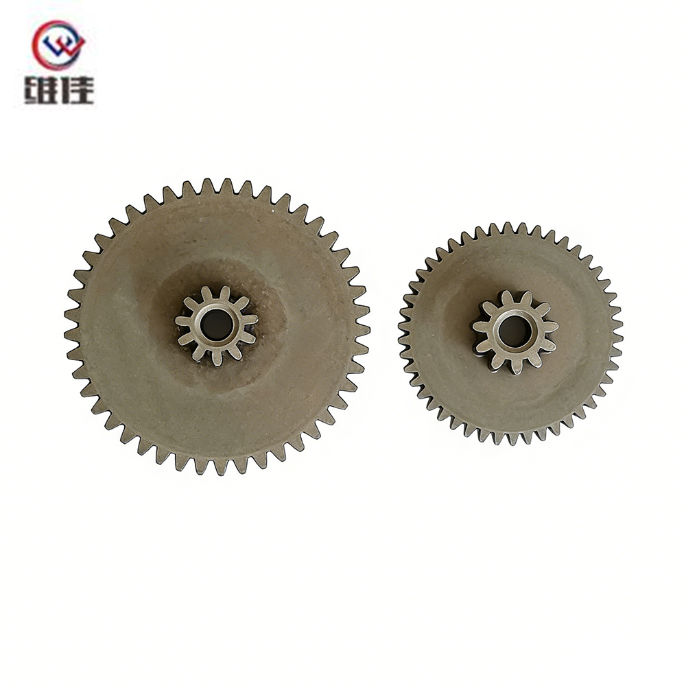
Product Overview
The M0.8 double pinion gear is produced from AB powder metallurgy material, described as a high-strength iron-based alloy suitable for precision structural parts. The manufacturing sequence includes powder compaction, sintering, precision machining, quenching and tempering, and final finishing. This combination of forming and post-processing allows the component to achieve a balance between dimensional stability, wear resistance, toughness, and production efficiency.
The large gear contains 46 teeth, while the small pinion contains 11 teeth. The two sections are manufactured as one integrated part rather than as separate gears joined during assembly. This configuration is useful in compact transmission systems where the spacing, phase relationship, and concentricity between the two gear sections must remain consistent.
The nominal hardness range after heat treatment is HRC 32–38. This range is intended to provide a practical balance between surface wear resistance and resistance to brittle failure. Excessive hardness can reduce toughness in small gear teeth, while insufficient hardness may lead to accelerated wear under repeated loading. The specified hardness range is therefore suitable for many moderate-load applications, subject to confirmation through application-specific engineering analysis.
Core Technical Specifications
| Parameter | Specification |
|---|---|
| Component type | Integrated double pinion gear |
| Large gear tooth count | Z46 |
| Small pinion tooth count | Z11 |
| Module | M0.8 |
| Small gear bore | 11 mm |
| Material | AB powder metallurgy, high-strength iron-based alloy |
| Heat treatment | Quenching and tempering |
| Hardness | HRC 32–38 |
| Primary production route | Powder compaction, sintering, precision machining, heat treatment, and finishing |
| Typical applications | Industrial machinery, automotive components, automation systems, appliances, and precision equipment |
The specifications above define the standard configuration. Tooth counts, module, bore size, heat treatment, density, surface treatment, and dimensional tolerances can be reviewed for customized projects. Final suitability should be evaluated according to torque, speed, duty cycle, lubrication, noise requirements, environmental conditions, and expected service life.
Integrated Double Pinion Design
A double pinion gear performs the work of two coordinated gear elements within one component. In a conventional arrangement, two separate gears may need to be manufactured, oriented, mounted, and checked individually. Each additional interface creates a possibility for assembly variation, phase error, runout, or axial movement. An integrated double pinion design reduces the number of interfaces and can simplify the overall transmission structure.
The Z46 and Z11 tooth combination supports a reduction relationship based on the difference in tooth count between the two sections. The large gear provides a greater number of teeth for controlled motion transmission, while the smaller 11-tooth pinion is suitable for driving or receiving motion in a compact mechanism. The exact speed ratio and torque requirement depend on the mating gear arrangement and the intended transmission architecture.
In small-module applications, even minor errors in tooth profile, concentricity, or phase alignment can create noticeable noise and vibration. An integrated structure helps maintain the relative position of the two gear sections because both are formed in the same die system. The result can be more predictable meshing and reduced need for corrective assembly procedures.
Advantages of One-Piece Construction
Improved alignment: The two gear sections are produced as part of the same component, reducing the risk of angular and radial misalignment between separately assembled parts.
Reduced assembly complexity: The customer may be able to eliminate separate fastening, pressing, staking, or alignment operations associated with two individual gears.
Consistent phasing: Multi-level tooling is used to maintain the angular relationship between the upper and lower gear sections. The supplied production information indicates a standard angular orientation capability within approximately ±0.5 degrees, with tighter control available on request.
Lower component count: A single double pinion can replace multiple individual components, potentially reducing inventory, handling, inspection, and assembly costs.
Stable transmission behavior: A rigid integrated structure can help maintain the designed gear relationship under normal operating conditions, provided the component is correctly supported and loaded.
Why Powder Metallurgy Is Suitable for M0.8 Gears
Powder metallurgy is a manufacturing technology in which metal powders are compacted in a precision die and then sintered under a controlled atmosphere. The process is particularly useful for high-volume parts with repeatable geometry, moderate dimensions, and a need for efficient material utilization.
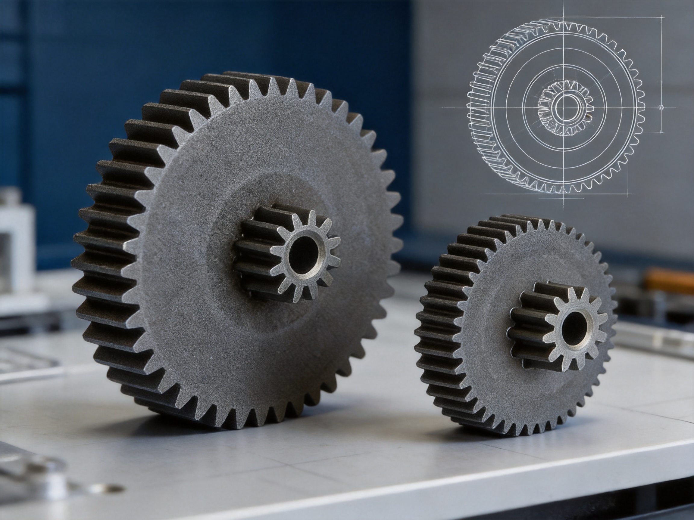
For small-module gears, the technology can produce complex profiles with less material waste than subtractive machining. The powder is placed close to the final component geometry before sintering. Instead of removing a large quantity of material from a solid steel blank, the process forms the gear near net shape and uses machining only where tighter tolerances or functional surfaces require it.
The use of powder metallurgy does not mean that every dimension is automatically achieved without post-processing. Critical bores, reference surfaces, tooth dimensions, and fit locations may require sizing, turning, reaming, or other precision operations. However, the amount of material removed is generally lower than in a fully machined manufacturing route.
Material Efficiency
Conventional machined steel gears normally begin with bar stock, a forged blank, or another oversized workpiece. Hobbing, shaping, turning, deburring, and other processes remove material as chips. Depending on the geometry and starting blank, material utilization may be approximately 45–60 percent, meaning that a substantial portion of the original material becomes scrap or requires recycling.
Powder metallurgy uses a controlled quantity of metal powder to form the part. The supplied production data indicates material utilization above 97 percent for this type of near-net-shape gear. The exact value depends on the powder formulation, component mass, reject rate, tooling design, and any subsequent machining allowance. Nevertheless, the reduction in material waste can be significant when production volumes reach tens or hundreds of thousands of pieces.
For a representative gear weighing approximately 12 grams, the reported comparison suggests that roughly 8–10 grams of material may be saved per part when compared with a machining-intensive steel route. At one million pieces, this can represent several metric tons of reduced material consumption, in addition to lower machining time and tool wear.
Repeatable Forming
Once the compaction tooling has been qualified, each press cycle reproduces the same basic geometry. This tool-controlled process is different from a machining process in which cutting tools gradually wear, operators adjust setups, and multiple operations must remain coordinated.
The repeatability of powder compaction depends on powder flow, die filling, lubrication, press control, punch movement, density distribution, and tooling condition. Advanced production controls are therefore important. Multi-action pressing can help compensate for changes in part height and geometry, while real-time density monitoring can assist in identifying process drift before it results in large quantities of nonconforming parts.
For a double pinion gear, uniform density is especially important. Density differences may contribute to dimensional variation, distortion during sintering, or local differences in strength. Proper die design and coordinated punch movement help achieve a more consistent structure across the large gear and small pinion sections.
Manufacturing Process
1. Powder Selection and Preparation
The manufacturing process begins with the selection of an iron-based powder formulation suitable for the required density, strength, machinability, and heat treatment response. The AB powder metallurgy material used for this product is identified as a high-strength iron-based alloy. Depending on the final engineering requirements, alloying elements may include copper, carbon, nickel, molybdenum, or other additions used in powder metallurgy systems.
The powder is blended with controlled quantities of alloying ingredients, lubricant, and processing aids. A uniform mixture is necessary to achieve consistent filling and stable mechanical properties. Powder characteristics such as particle size distribution, apparent density, flowability, compressibility, and oxygen content can influence the compaction process.
Production control at this stage is important because variations in powder composition may affect green density, sintering shrinkage, hardness, machinability, and fatigue performance. Material certification and batch traceability provide a foundation for later process control and customer documentation.
2. Precision Die Compaction
During compaction, the prepared powder is placed into a precision die cavity that reproduces the external form of the gear. Press punches apply controlled pressure to consolidate the powder into a temporary shape known as a green compact.
The double pinion geometry requires careful control because the large gear, small pinion, bore, and connecting sections may have different cross-sectional areas. A poorly balanced design can produce density gradients or stress concentrations. Multi-level punches and multi-action pressing are used to fill and compress different sections in a controlled manner.
Tooling is manufactured from wear-resistant materials, with precision carbide dies available for demanding geometries. The die set must provide accurate tooth form, stable alignment, suitable draft angles, controlled ejection, and adequate resistance to repeated press cycles.
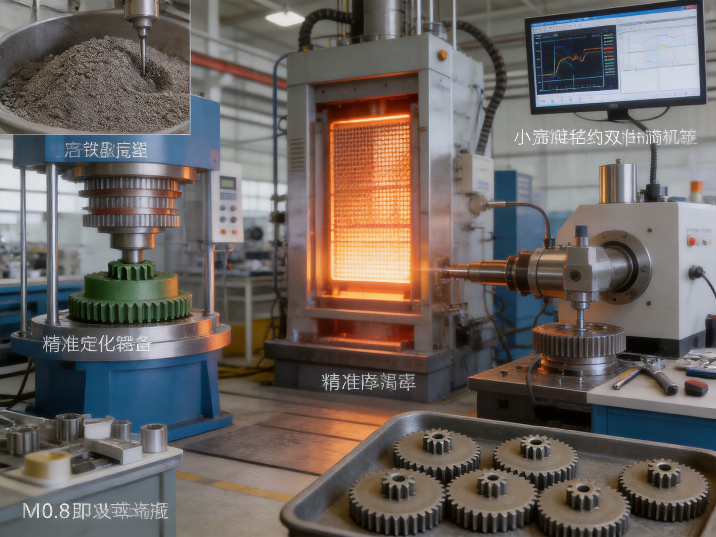
The supplied production information identifies the use of CNC compaction presses with real-time density monitoring. This type of equipment can support closed-loop control and process documentation. Press displacement, compaction force, fill height, ejection behavior, and density-related parameters can be monitored to maintain stable production.
3. Sintering
The green compact is transferred to a controlled-atmosphere sintering furnace. During sintering, the component is heated below its melting point so that the powder particles bond through diffusion. The part develops its basic mechanical integrity, strength, and final metallurgical structure during this stage.
Sintering temperature, atmosphere, belt speed, dew point, carbon potential, loading arrangement, and cooling conditions all influence the final result. The furnace must provide stable conditions across the working zone because variations can produce inconsistent shrinkage or hardness.
The supplied process information describes mesh-belt furnaces with temperature uniformity of approximately ±5 degrees Celsius. Controlled furnace conditions help reduce distortion and improve repeatability from batch to batch. The exact dimensional change after sintering depends on powder composition, green density, geometry, tooling compensation, and furnace conditions.
For small gears, distortion control is especially important because tooth spacing and bore alignment directly affect meshing. A stable sintering profile reduces the need for extensive corrective machining and supports consistent transmission performance.
4. Precision Machining and Sizing
Powder metallurgy can form most of the external gear geometry, but selected surfaces may require precision machining. The bore, reference faces, bearing seats, or other functional locations may be sized to achieve the required fit and concentricity.
Sizing is a controlled repressing operation that improves dimensional accuracy by passing the sintered component through a sizing die. The supplied production information indicates that optional sizing can be used for applications requiring higher accuracy, including target performance comparable to ISO grade 7 in suitable configurations.
Not every application requires the same level of finishing. As-sintered parts may be appropriate for many cost-sensitive mechanisms, while high-speed, low-noise, or tightly fitted assemblies may benefit from additional sizing, machining, or surface treatment. This flexibility allows the manufacturing route to be matched to the actual performance requirement rather than applying unnecessary operations to every part.
5. Quenching and Tempering
The gear is heat treated through quenching and tempering to achieve the specified hardness range of HRC 32–38. Quenching rapidly cools the heated component to transform the material structure, while tempering reduces excessive internal stress and improves toughness.
Heat treatment must be carefully controlled because small gears can be sensitive to deformation. Furnace temperature, holding time, quenching medium, transfer time, agitation, and tempering conditions all influence the final result. A controlled process minimizes the risk of tooth distortion, bore change, cracking, and uneven hardness.
The objective is not simply to maximize hardness. A gear tooth must resist wear while also tolerating repeated bending and contact loads. The HRC 32–38 range provides a balanced target for many moderate-load applications. For applications involving high torque, shock loading, severe wear, or elevated temperature, a detailed design review may be required to determine whether a different alloy or treatment is more appropriate.
6. Finishing and Optional Surface Treatments
After heat treatment, the gear may receive final cleaning, deburring, dimensional inspection, or additional surface treatment. Steam treatment is available as an option for improving corrosion resistance and providing slight surface hardening. It may also help stabilize the surface appearance and support performance in certain lubricated or mildly humid environments.
Other finishing requirements can include oil impregnation, protective coating, controlled washing, rust prevention, or customer-specific packaging. The correct option depends on the application environment, storage conditions, lubricant, and assembly process.
Performance Advantages Compared with Machined Steel Gears
Lower High-Volume Production Cost
The principal economic advantage of powder metallurgy becomes apparent in repeated production. Tooling costs must be considered at the beginning of a project, but once the die has been qualified, each additional part can be produced with relatively short press cycles and limited material waste.
The supplied comparison estimates a piece-part cost of approximately 0.28–0.45 US dollars for the powder metallurgy version at a volume of 500,000 pieces per year, compared with approximately 0.65–0.90 US dollars for a machined steel equivalent. The estimated reduction is approximately 40–55 percent. Actual pricing depends on material, tolerances, heat treatment, tooling amortization, packaging, inspection, logistics, and order volume.
For annual volumes above approximately 20,000–30,000 pieces, powder metallurgy may begin to offer an economic advantage, depending on the complexity of the gear and the amount of conventional machining required. At 50,000 pieces or more per year, the cost benefit is often more apparent. The ideal production volume should be calculated from the customer’s drawing, forecast, tolerance requirements, and expected program duration.
Shorter Production Cycle
A machined double pinion gear may require turning, hobbing, shaping, deburring, cleaning, inspection, and potentially grinding. If the two gear sections cannot be produced in one setup, additional handling and alignment operations may be necessary. The supplied comparison estimates a total cycle time of approximately 45–90 seconds per machined gear.
Powder compaction and sintering can reduce the forming cycle to approximately 6–8 seconds per gear when considered as a high-volume production sequence, excluding heat treatment and certain downstream operations. This represents a potential seven- to ten-fold reduction in the main forming cycle. Shorter cycle times can reduce labor content, machine occupancy, energy allocation per part, and production lead time.
Improved Material Utilization
Near-net-shape forming places material where it is needed instead of removing most of the gear from a solid blank. Material utilization above 97 percent is reported for the powder metallurgy route. This can reduce raw material consumption and lower exposure to fluctuations in steel prices.
Material efficiency also supports more sustainable production by reducing chip generation and the energy associated with cutting, transporting, cleaning, and recycling machining waste. Although powder metallurgy still consumes energy during powder production, compaction, and sintering, the total environmental profile must be evaluated across the complete process rather than by considering any single operation in isolation.
Consistent Tooth Geometry
The supplied technical comparison reports tooth-to-tooth spacing variation of approximately ±0.008–0.012 mm for precision-compacted, as-sintered parts, compared with approximately ±0.015–0.025 mm for typical hobbed steel gears. These figures are representative process values rather than universal guarantees, and the final capability depends on the drawing, gear geometry, tooling, inspection method, and production conditions.
Pitch circle runout is reported at approximately 0.015–0.025 mm for the as-sintered powder metallurgy component, with optional sizing capable of reducing runout to approximately 0.008–0.012 mm under suitable conditions. Lower runout can contribute to more uniform meshing, lower transmission error, reduced vibration, and less gear noise.
The powder metallurgy process is tool-based, so the first acceptable part and a later part in the same qualified production run can be highly similar. Machining processes may experience gradual tool wear, requiring more frequent adjustments and inspections. A stable forming process can therefore simplify production control for long-term programs.
Reduced Secondary Operations
Machined steel gears commonly require deburring after cutting. Depending on the desired accuracy and surface quality, additional grinding or finishing may be required. The powder metallurgy gear can emerge from the forming and sintering process with a near-net tooth profile, reducing the number of operations.
The supplied comparison indicates that powder metallurgy may eliminate three or four secondary operations in comparison with a machined steel route. Some applications may require no additional sizing, while others may require one sizing operation or localized machining. Selecting only the necessary post-processing steps helps maintain cost efficiency without compromising critical performance characteristics.
| Comparison Parameter | Machined Steel Gear | Powder Metallurgy Gear |
|---|---|---|
| Material utilization | Approximately 45–60% | More than 97% in the reported near-net-shape process |
| Main forming cycle | Approximately 45–90 seconds | Approximately 6–8 seconds for compaction and sintering sequence |
| Estimated piece-part cost at 500,000 pieces per year | Approximately $0.65–$0.90 | Approximately $0.28–$0.45 |
| Tooth spacing variation | Approximately ±0.015–0.025 mm | Approximately ±0.008–0.012 mm as reported |
| Typical pitch runout | Approximately 0.025–0.045 mm | Approximately 0.015–0.025 mm as-sintered |
| Potential runout after sizing | Depends on grinding and setup | Approximately 0.008–0.012 mm under suitable conditions |
| Process capability for critical dimensions | Reported typical Cpk of 0.9–1.1 | Reported typical Cpk of 1.3–1.6 |
| Secondary operations | Deburring, cleaning, and possible grinding | None or one sizing operation for many applications |
Quality Control and Production Reliability
Consistent gear quality depends on control of the complete process rather than on final inspection alone. A reliable supplier must manage material preparation, tooling, press settings, sintering, heat treatment, machining, surface treatment, and packaging as an interconnected production system.
The manufacturer operates an approximately 13,039-square-meter production base and has more than 20 years of experience in powder metallurgy and related precision machining. The company employs more than 150 skilled personnel and maintains production equipment that includes high-efficiency presses, high-temperature sintering furnaces, and precision forming machines.
Quality management is supported by ISO 9001:2015 and IATF 16949:2016 certifications. These systems provide a structured framework for process documentation, corrective action, traceability, customer requirements, internal audits, and continual improvement. Certification does not replace product-specific validation, but it demonstrates that the organization has established formal quality procedures.
Inspection and Testing Activities
Inspection may include dimensional measurement of the bore, outside diameter, gear thickness, reference faces, tooth thickness, and overall height. Runout and concentricity checks are important because the gear must rotate predictably around its mounting axis.
Gear roll testing can be used to identify runout, meshing irregularity, and functional transmission errors. The supplied manufacturing information indicates 100 percent gear roll testing for runout on applicable production programs. Statistical process control is used for important dimensions such as tooth thickness and bore diameter, with process capability data available by batch.
Material and heat treatment verification may include density testing, hardness measurement, metallographic examination, tensile or bending evaluation, and dimensional inspection before and after heat treatment. The exact test plan should be determined by the customer drawing, specification, applicable standards, and risk level of the finished assembly.
Process Capability
The reported Cpk range of 1.3–1.6 for a key dimension such as gear outside diameter indicates a potentially capable and stable process when the stated conditions are maintained. Cpk values must always be interpreted together with the tolerance range, sample size, measurement system capability, and production period.
Real-time monitoring of press force, displacement, and density-related parameters can identify abnormal trends early. Furnace temperature recording, atmosphere control, and batch traceability help connect final product results with the conditions under which each lot was produced.
Tool maintenance is another important factor. Gear dies and punches experience repeated mechanical and thermal stress. Regular inspection of tooth-form tooling, die alignment, punch wear, and ejection components helps prevent gradual dimensional drift. Preventive maintenance also reduces the likelihood of unexpected production interruptions.
Applications
Industrial Automation
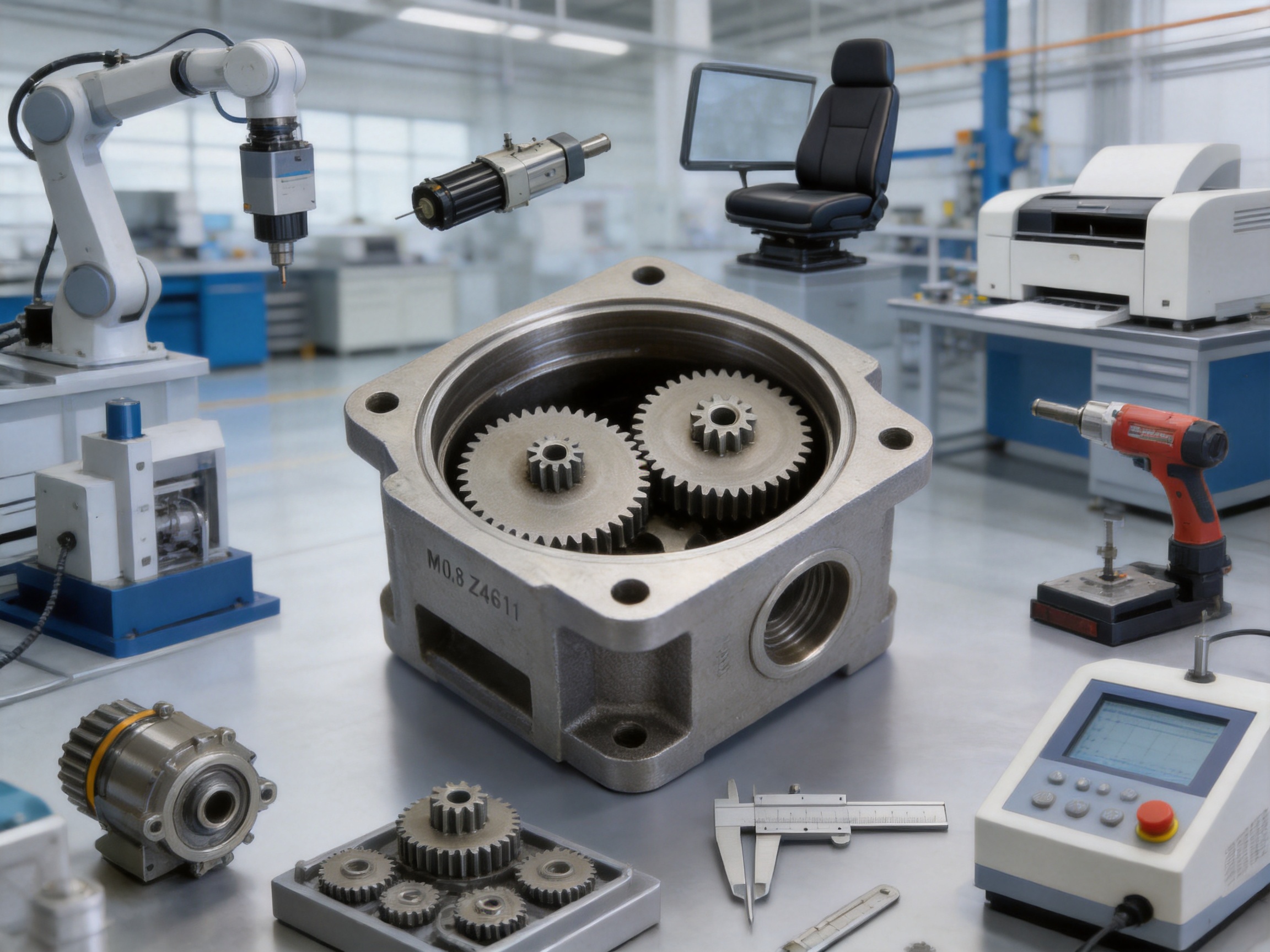
Robotic mechanisms, conveyor systems, small actuators, positioning modules, and CNC auxiliary systems often require compact gears that can operate repeatedly with limited maintenance. The integrated double pinion configuration can simplify the transmission layout and help reduce the number of alignment-sensitive components.
In automation equipment, repeatability is often as important as maximum torque. A gear with stable tooth spacing and low runout can support predictable movement and reduce positional variation. The appropriate grease, oil, or dry-film lubricant should be selected according to speed, load, temperature, and enclosure conditions.
Automotive Components
Automotive seat adjusters, window lifters, small actuators, latching mechanisms, and other auxiliary systems use compact gear drives that may be produced in large quantities. These applications value low unit cost, reliable operation, controlled noise, and stable performance across repeated cycles.
The IATF 16949 quality system is relevant to automotive supply chains because it supports process planning, risk analysis, traceability, and continual improvement. Automotive customers may also require additional validation, endurance testing, material documentation, cleanliness control, and specific submission procedures.
Power Tools
Electric drills, grinders, saws, and similar tools can place repeated loads on small transmission components. The M0.8 double pinion gear may be suitable for selected mechanisms where the torque and impact conditions are within the capability of the material and heat treatment.
Power tool applications should be reviewed carefully because shock loading, rapid acceleration, high rotational speed, and elevated operating temperatures may exceed the requirements of office equipment or small household machinery. Where high torque or severe impact is expected, the manufacturer can perform a joint engineering review and evaluate higher-density materials, alternative alloy systems, or different heat treatments.
Office and Household Appliances
Printers, copiers, scanners, small kitchen appliances, cleaning equipment, and household actuators often contain compact gear trains with demanding requirements for low noise and long operating life. Production volumes may be high, making material utilization and cycle time major cost factors.
The integrated structure can also simplify assembly and reduce the risk of incorrect gear phasing. Controlled tooth geometry helps maintain smooth motion in mechanisms that are frequently located close to the user or in environments where gear noise is noticeable.
Precision Instruments
Medical devices, optical systems, laboratory instruments, and measuring equipment may use small gears for positioning or adjustment. In these applications, dimensional stability, clean manufacturing, controlled backlash, and predictable movement are often more important than maximum power transmission.
Specific requirements may include special cleaning, low-particle packaging, corrosion protection, nonmagnetic material selection, or documented inspection results. These needs should be defined during the product development stage so the powder formulation and post-processing route can be selected appropriately.
Customization and Engineering Support
The standard configuration uses Z46 and Z11 tooth counts, module 0.8, and an 11 mm small gear bore. However, powder metallurgy tooling can be adapted for customer-specific designs. Possible modifications include tooth count, module, bore diameter, external diameter, gear width, hub geometry, keyways, reliefs, chamfers, stepped sections, and mounting features.
Hardness and density can also be reviewed according to the required load and wear performance. The manufacturer can consider alternative iron-based alloy systems such as Fe-Cu-C or Fe-Ni-Mo-C when higher strength or fatigue resistance is required. Material selection should be based on actual loading conditions rather than on hardness alone.
Customers should provide a technical drawing or sample whenever possible. Useful information includes the mating gear specification, operating speed, transmitted torque, duty cycle, expected life, lubrication method, temperature range, environmental exposure, noise limit, mounting configuration, and dimensional tolerances.
A design review can determine which dimensions should remain as-sintered, which surfaces require sizing, and which locations need precision machining. This approach prevents overengineering and helps achieve the required performance at the lowest practical production cost.
Tooling Considerations
Powder metallurgy requires an initial investment in dies, punches, and related tooling. Tooling design must consider powder flow, compaction direction, ejection, tooth geometry, density distribution, shrinkage, and service life. The tooling cost is normally amortized across the expected production quantity.
Tooling is most economical when the program has a stable forecast and a sufficiently long production life. The supplied guidance recommends evaluating powder metallurgy for annual quantities above approximately 20,000–30,000 pieces, although the exact break-even point depends on part complexity and machining alternatives.
The company can provide tooling amortization options and a cost comparison based on the customer’s drawing and volume forecast. A preliminary quotation should distinguish one-time tooling charges from recurring piece-part costs, inspection charges, packaging, and optional post-processing.
Installation and Application Guidelines
Correct installation is essential for achieving the expected life of any small gear. The 11 mm bore should be checked against the shaft diameter, fit class, surface finish, and alignment requirement. Excessive interference can distort the gear, while excessive clearance can cause movement, noise, or uneven loading.
The mating gear should have compatible module, pressure angle, tooth profile, and center distance. Incorrect center distance can cause high contact stress, backlash, or tooth interference. The mounting structure should support the gear adequately and prevent excessive shaft deflection.
Lubrication should be selected according to speed, load, temperature, materials, sealing, and service environment. Insufficient lubrication may accelerate wear, while incompatible grease or excessive lubricant may affect nearby components. For enclosed systems, the gear, lubricant, bearing, and housing should be evaluated as one transmission system.
During commissioning, engineers should check rotation resistance, noise, backlash, temperature rise, contact pattern, and vibration. If the gear operates near its load limit, endurance testing under representative conditions is recommended before full-scale production approval.
Frequently Asked Questions
What does M0.8 mean in this gear?
M0.8 refers to the gear module, which defines the relationship between tooth size and pitch diameter in metric gear design. A module of 0.8 represents a relatively small tooth size suitable for compact mechanisms. The mating gear must use a compatible module and pressure angle for proper engagement.
What are the tooth counts of the double pinion gear?
The standard component has a large gear with 46 teeth and a small pinion with 11 teeth. The two sections are integrated into one double pinion component. Customized tooth counts may be reviewed according to the customer’s transmission design.
What material is used?
The product is made from AB powder metallurgy material, identified as a high-strength iron-based alloy. Alternative powder metallurgy alloy systems may be considered when the application requires higher density, greater fatigue strength, different machinability, or specific heat treatment behavior.
What hardness can be expected?
The standard heat-treated hardness is HRC 32–38. This range is intended to balance wear resistance and toughness. The suitable hardness depends on tooth load, speed, impact, lubrication, and required service life, so application-specific validation is recommended.
Can this gear replace a machined steel gear directly?
It may replace a machined steel gear when the geometry, strength, density, hardness, tolerance, and operating conditions are compatible. Direct substitution should not be assumed solely from the external dimensions. The mating gear, shaft fit, torque, duty cycle, temperature, and failure mode should be reviewed before approval.
Is the double pinion gear manufactured as one piece?
Yes. The large gear and small pinion are formed as an integrated component. This construction reduces assembly interfaces and can improve phase consistency between the two gear sections.
How accurate is the gear?
Reported process values include tooth spacing variation of approximately ±0.008–0.012 mm for precision-compacted as-sintered parts and pitch runout of approximately 0.015–0.025 mm. Optional sizing may reduce runout to approximately 0.008–0.012 mm under suitable production conditions. Final accuracy depends on the approved drawing and inspection standard.
Is sizing always required?
No. Many applications can use the gear in an as-sintered or lightly finished condition. Sizing is recommended when tighter dimensional control, improved concentricity, or a more precise fit is required. The decision should be made after reviewing the functional tolerances of the assembly.
What is the minimum order quantity?
The economic quantity depends on tooling cost, geometry, tolerance, and the alternative manufacturing route. As general guidance, annual volumes above approximately 20,000–30,000 pieces may justify powder metallurgy, while volumes above 50,000 pieces often provide a clearer unit-cost advantage. A detailed cost comparison should be prepared from the customer’s forecast.
Can the material withstand high torque?
For many small actuators, office automation systems, automotive auxiliary mechanisms, and similar applications, heat-treated powder metallurgy material can provide sufficient performance. The supplied information indicates bending fatigue strength of approximately 300–400 MPa for certain heat-treated PM systems. High-torque or severe-impact applications require engineering review, validation testing, and possibly a higher-density alloy.
How is phase alignment between the two pinions controlled?
The double pinion is compacted in a single die cavity using a multi-level punch system. This tooling approach establishes the relative angular orientation during forming. The supplied standard capability is approximately ±0.5 degrees, with tighter control available on request. Sizing can correct certain minor dimensional deviations but should not be viewed as a substitute for correct die design.
What quality certifications does the manufacturer hold?
The manufacturer reports ISO 9001:2015 and IATF 16949:2016 certifications. These systems support documented quality management, process control, corrective action, traceability, and continual improvement. Additional customer-specific audits and validation requirements can be addressed during project development.
Supplier Strengths
Jiande Welfine Technology Co., Ltd. has operated since 2001 and focuses on powder metallurgy sintering, self-lubricating bushings, structural parts, and precision components. Its experience includes product development based on customer drawings or samples, which is valuable for projects that require customized gear geometry or a combination of powder forming and machining.
The company’s production base covers approximately 13,039 square meters and includes high-efficiency compaction presses, high-temperature sintering furnaces, precision forming equipment, and inspection resources. More than 150 employees support research and development, manufacturing, quality management, and customer service.
A broad powder metallurgy capability allows the supplier to support more than one type of component. This can be beneficial to customers seeking a common manufacturing partner for gears, hubs, bushings, friction components, magnetic parts, and other sintered metal products.
The company’s manufacturing strengths include near-net-shape forming, multi-action compaction, controlled-atmosphere sintering, precision machining, heat treatment, sizing, steam treatment, statistical process control, and gear roll testing. These capabilities support both standard production and OEM/ODM development projects.
Conclusion
The M0.8 Z46/Z11 powder metallurgy double pinion gear is designed for compact, repeatable, and cost-sensitive transmission systems. Its integrated two-gear structure reduces assembly complexity and helps maintain the relationship between the large gear and small pinion. The 11 mm bore supports practical shaft mounting, while the HRC 32–38 heat treatment range provides a balanced combination of wear resistance and toughness for many moderate-load applications.
The powder metallurgy process offers meaningful advantages over conventional machined steel production when quantities are sufficiently high. Near-net-shape forming can achieve material utilization above 97 percent, shorten the main forming cycle, reduce secondary operations, and improve consistency across long production runs. Reported improvements in tooth spacing variation, pitch runout, and process capability further support applications where smooth transmission and stable quality are important.
The component is suitable for industrial automation, automotive auxiliary systems, office equipment, power tools, appliances, and precision instruments, provided that its load and environmental requirements are properly validated. Customized tooth counts, bore sizes, materials, hardness levels, and finishing operations can be considered for OEM applications.
With more than two decades of powder metallurgy experience, a modern production base, controlled sintering and compaction equipment, ISO 9001:2015 and IATF 16949:2016 certification, and support for precision machining and heat treatment, Jiande Welfine Technology Co., Ltd. provides an integrated manufacturing solution for customers seeking reliable, scalable, and cost-effective double pinion gears.
References
1. Jiande Welfine Technology Co., Ltd., product specification and manufacturing information for the AB powder metallurgy double pinion gear, Z46/Z11, M0.8.
2. Jiande Welfine Technology Co., Ltd., company profile, production capabilities, quality certifications, and OEM/ODM service information.
3. ISO 9001:2015, Quality Management Systems—Requirements.
4. IATF 16949:2016, Quality Management System Requirements for Automotive Production and Relevant Service Parts Organizations.
5. Powder Metallurgy Association, general principles of powder compaction, sintering, sizing, and powder metallurgy design.
6. Standard engineering practice for involute gear design, gear inspection, tooth spacing, runout, backlash, and transmission performance.
Product: AB Powder Metallurgy Double Pinion Gear (Z46/Z11, M0.8)
Related products
-
-
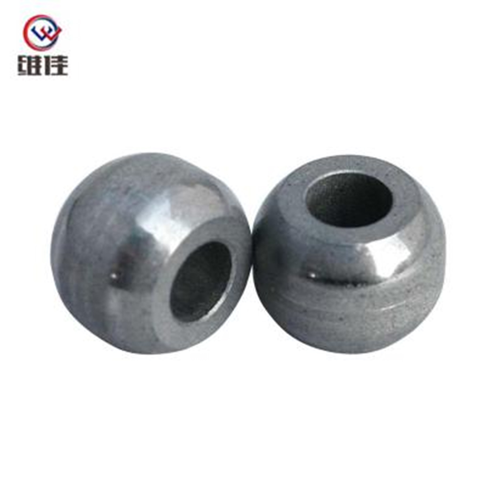
Product Description: High-precision powder metallurgy part (S14*7*10) made of iron material from Jiande Wefine, customized PM components with strict tolerance control.
See Details -
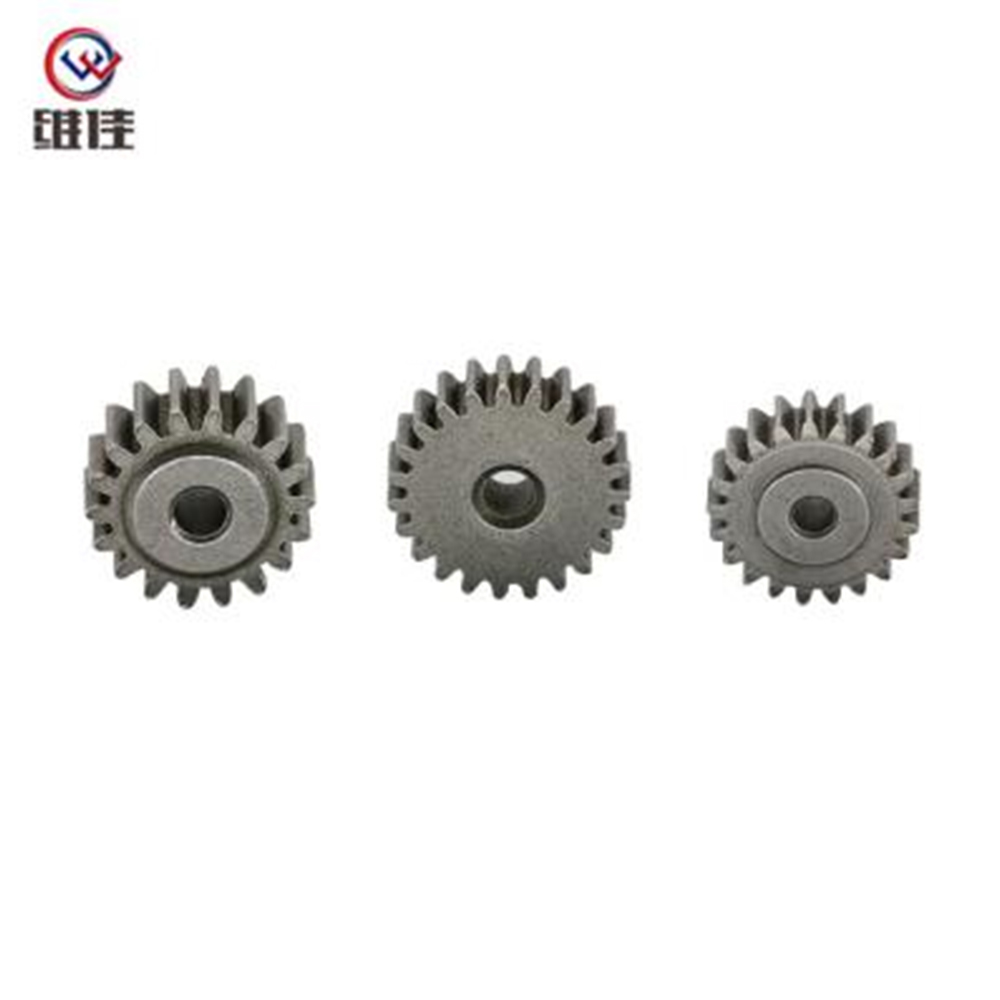
Description: Custom powder metallurgy planetary gear with high precision, wear resistance for automotive, industrial machinery & home appliances. OEM/ODM supported.
See Details -
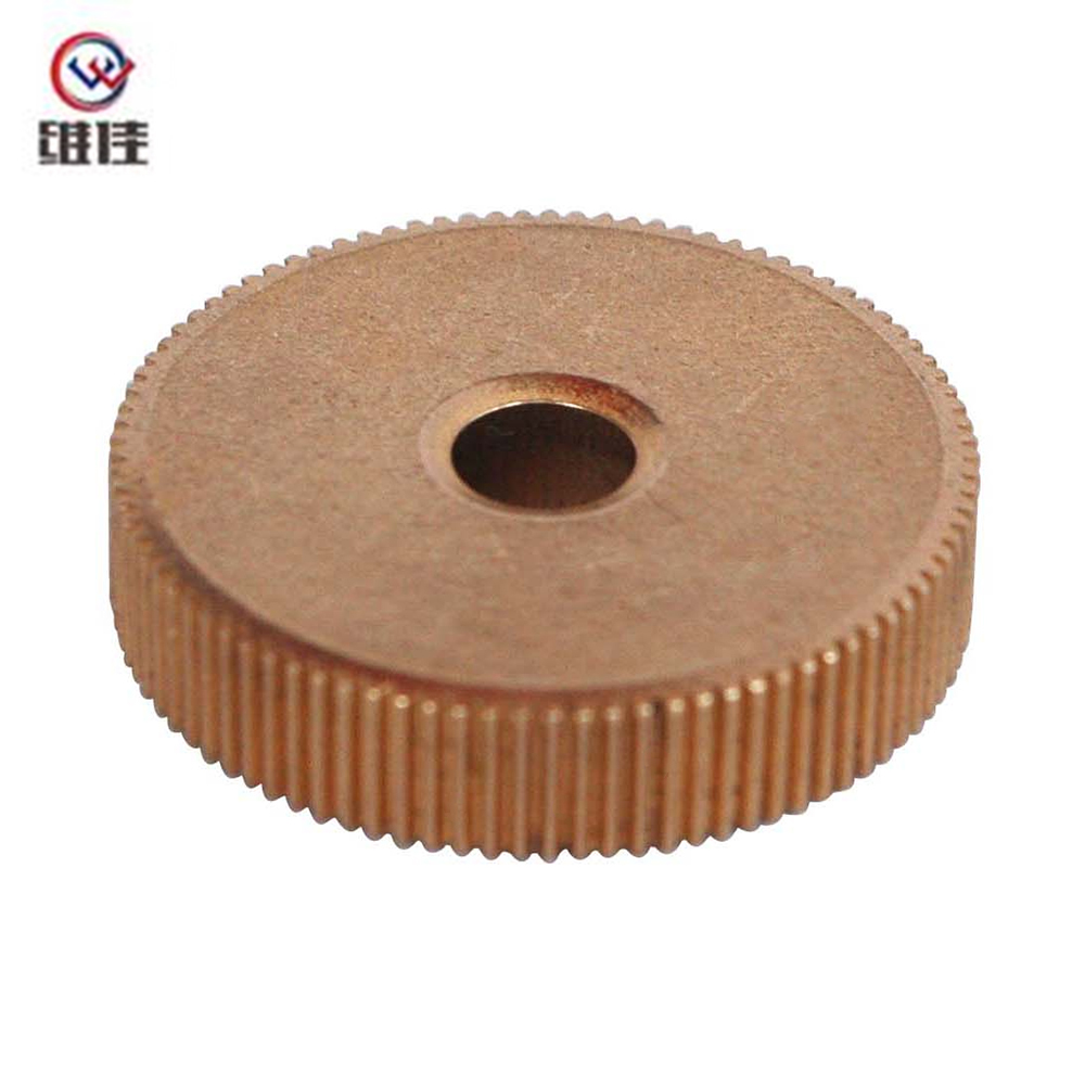
This 4×11.5×5.2mm powder metallurgy gear is manufactured through a precise press-sinter-through hole-oil impregnation process, with strict control of press density (6.7–6.8g/cm³) and sintering tempera...
See Details -
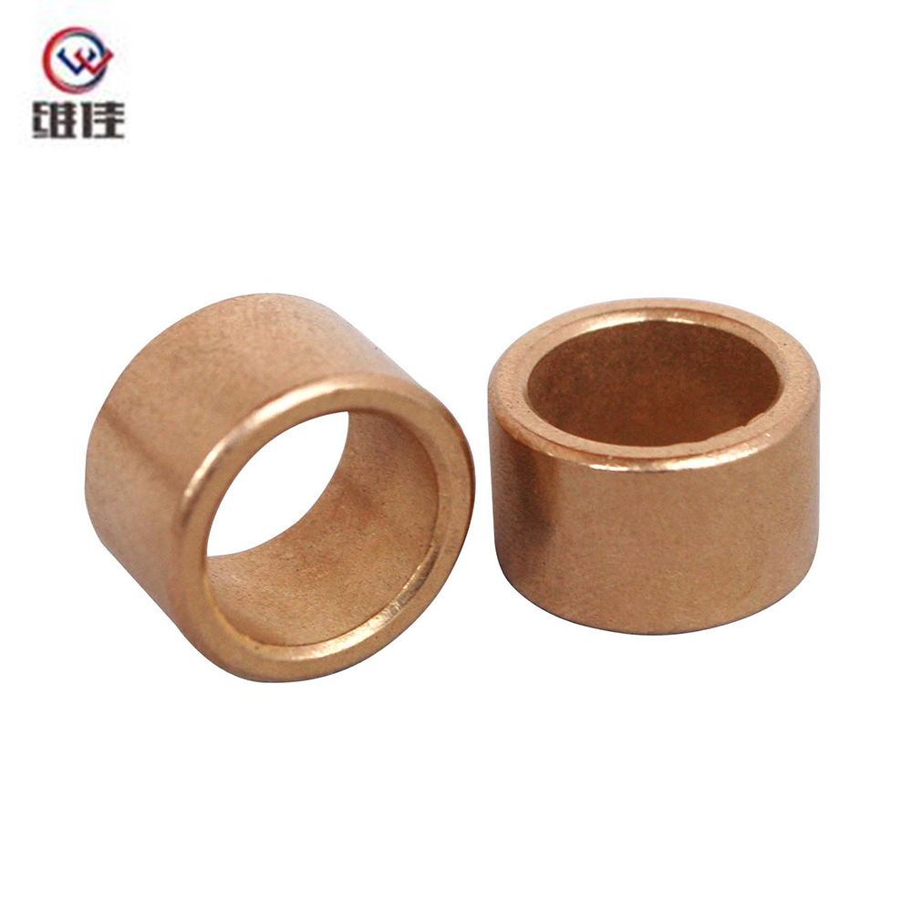
This copper-based powder metallurgy bushing is manufactured through an integrated process of compaction, sintering, sizing, and oil impregnation. It features excellent wear resistance and self-lubrica...
See Details
Copyright © Jiande Welfine Technology Co., Ltd. All Rights Reserved. Privacy Custom Self-lubricating Sintered Bushing Manufacturers
